Namely these are the valve body valve spool actuator and spring.
Hydraulic directional control valve symbols pdf.
The grooves also allow gas or oil to flow around the given spool at the same time through valve body.
Most of the lands often block oil flow that flow through the body of the valve.
Hydraulic directional control valve.
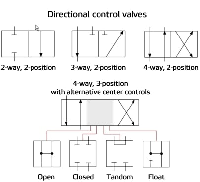
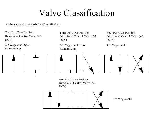
As with all fluid power components directional control valves can be represented by standard symbols published in iso 1219.
Hydraulic directional valve symbols introduction.
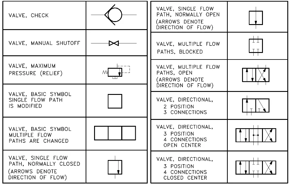
Perhaps the simplest of all directional control valves is the check valve a specific type of binary valve.
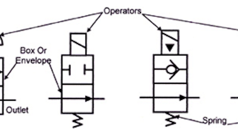
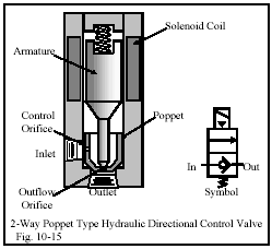
A directional control valve broadly consists of four parts.
The spool mounted in the directional valves common known as sliding type often consists of lands as well as grooves.
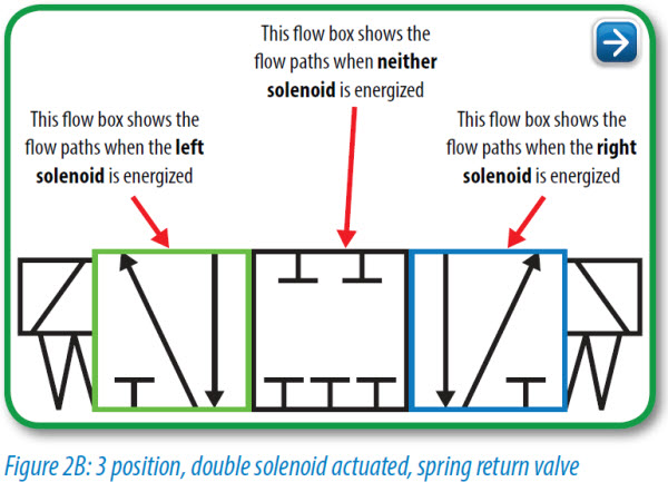
Each position the valve can take is represented by a square.
Basics of the iso symbols.
In 4 3 way directional valves the centre position of the control.
These directional valves consist of a housing 1 control spool 2 control mechanism 3 and return spring 4.
Inlet outlet and exhaust or tank.
Schemes of directional valves the description of directional valves is standardized by din iso 121.
1 2 1 6 this standard provides basic symbols which differentiate between hydraulic and pneumatic fluid power media.
Composite symbols can be devised for any fluid power component by combining basic symbols.
Simplified symbols are shown for commonly used components.
The valve spool get shifted with respect to the valve body which opens or closes valve ports.
3 way directional control valves a 3 way valve has three working ports.
Basic check valves allow fluid to flow in one direction but prevent fluid from flowing in the opposite direction.
Figures 8 5 through 8 10 show schematic symbols for 3 way directional control valves.
Hydraulic schematic symbols directional control valve 4 ports 2 positions directional control valve with 4 ports and 2 finite postions directional control valve 4 ports 3 positions directional control valve with 4 ports and 3 finite postions center position can have various flow paths directional control valve 5 ports.
The direction of hydraulic fluid flow is controlled by a directional control valve.
The iso symbols display only the function of the valves.